
Monday, October 29, 2007
Revit MEP Blog
Kyle Bernhardt of Autodesk has started a new Revit MEP blog called Inside the System. Check it out. It already has 3 great videos on creating view filters, and creating systems inside of Revit MEP.
Wednesday, October 17, 2007
Gearing Up for Birmingham CAD Camp!
Alacad will be hosting CAD Camp in Birmingham, AL on Thursday November 8th. I have just finished my courseware for this event and I think it will be an outstanding day of learning. Plan to attend if you are in the area.
Here is the line up for the Architecture and Building track.
Check out the complete course descriptions at www.cadcamp.com/birmingham.
Register TODAY!
Here is the line up for the Architecture and Building track.
- AutoCAD Architecture 2008 - Making Spaces Work For You! (revised and improved from last year)
- Revit Architecture 2008 - Design Options - Existing and Beyond
- Revit Architecture, Revit MEP, Revit Structure 2008 - Completing the BIM Model - Collaboration Across Disciplines
- Revit Architecture 2008 - Raising the Roof - Creating Roofs in Revit
- Revit Architecture 2008 and AutoCAD Civil 3D - From Dirt to Doors – Making Civil 3D and Revit Work Together
Check out the complete course descriptions at www.cadcamp.com/birmingham.
Register TODAY!
Friday, September 21, 2007
Revit and Google Earth
If you are a subscription customer using Revit, then listen up. Autodesk has finally posted their Google Earth extension that you can download to add your project to Google Earth or bring a Google Earth image into your project. Simply log into your subscription site and look for the Revit Globe - Link. You will find it on the "Autodesk Building Solutions Product Modules, Add-Ons, and Enhancement" page.


 If you want to publish your 3D model into Google Earth, you will need to switch to a 3D view in Revit and use the Publish to Google Earth tool. This will add a Temporary Place to your list inside of Google Earth. You can then zoom and orbit to see how your building fits within its context.

Once you have installed this, it will load some new commands to your Tools pulldown menu.
You must have Google Earth downloaded, installed, and running to use these tools. If you want to bring in an image from Google Earth, simple navigate to your site in Google Earth, then switch to Revit and use the Acquire from Google Earth tool. It works great for creating a site plan with the surrounding terrain.
If you want to publish your 3D model into Google Earth, you will need to switch to a 3D view in Revit and use the Publish to Google Earth tool. This will add a Temporary Place to your list inside of Google Earth. You can then zoom and orbit to see how your building fits within its context. This is just a quick example of how you can begin to move your model to a site.
I will take this opportunity to advertise for one of the Autodesk University classes that I will be assisting with. It is not being advertised very well to the architectural community because it is listed in the Civil track. I am teaching "From Dirt to Doors" with my in-house Civil guru, Jason Hickey. Check it out the description below and sign up for it.
I will take this opportunity to advertise for one of the Autodesk University classes that I will be assisting with. It is not being advertised very well to the architectural community because it is listed in the Civil track. I am teaching "From Dirt to Doors" with my in-house Civil guru, Jason Hickey. Check it out the description below and sign up for it.
Revit Wall Library
Are you trying to set up Revit Architecture for your company? If so, creating wall families can be a time consuming part of your task. I have a possible short cut for you. USG's web site has lots of walls, acoustical ceilings, and custom ceilings available for you to download. They have created just about their entire library of walls and ceilings in Revit format that you can download for free.


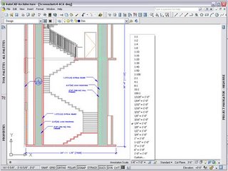
This brings up a good topic to discuss... How are you creating wall libraries? I have worked with several firms that are trying to tackle this issue. Your first thought might be to simply load them into your standard template. That is okay if you don't mind working in a large template with extra families that may never be used. Walls are project created families. You cannot have external files of walls like you do for other families (i.e. doors, windows, furniture.) I have found that the easiest way to have a library of walls is to create a separate project that is stored on your network that has nothing but wall families created in it. Users can open this project and find the wall they want to use and simply use the Copy/Paste command to copy the wall to their current project. I would create a view in this "wall project" that lists all the walls in an order that everybody understands. It could be similar to the way USG has created their files, as shown below.

I think manufacturers are finally realizing that Revit is here, and here to stay. I look forward to other companies making Revit content available in addition to the standard .dwg format. But until all manufacturers grasp this concept, you can continue to use my two favorite web sites to grab content for your project. If you have not already, check out Revit City and BIM World. They contain lots of information. Just be careful what you get for free, because sometimes what looks correct is not always the case. For example, I am working with my church to develop plans for a new multi-purpose building, and I downloaded a basketball court to use. Lo and behold, when I pulled down my nifty Graphic Standards, I found that the court was 10' too small.
You can download the entire wall library, or search for a particular wall that meets your needs. Once downloaded, you will see that they are .rvt files (Revit Template files). You can start a new project, and browse to open the particular template that you are looking for. Here is a view of the available wall templates.
This brings up a good topic to discuss... How are you creating wall libraries? I have worked with several firms that are trying to tackle this issue. Your first thought might be to simply load them into your standard template. That is okay if you don't mind working in a large template with extra families that may never be used. Walls are project created families. You cannot have external files of walls like you do for other families (i.e. doors, windows, furniture.) I have found that the easiest way to have a library of walls is to create a separate project that is stored on your network that has nothing but wall families created in it. Users can open this project and find the wall they want to use and simply use the Copy/Paste command to copy the wall to their current project. I would create a view in this "wall project" that lists all the walls in an order that everybody understands. It could be similar to the way USG has created their files, as shown below.
I think manufacturers are finally realizing that Revit is here, and here to stay. I look forward to other companies making Revit content available in addition to the standard .dwg format. But until all manufacturers grasp this concept, you can continue to use my two favorite web sites to grab content for your project. If you have not already, check out Revit City and BIM World. They contain lots of information. Just be careful what you get for free, because sometimes what looks correct is not always the case. For example, I am working with my church to develop plans for a new multi-purpose building, and I downloaded a basketball court to use. Lo and behold, when I pulled down my nifty Graphic Standards, I found that the court was 10' too small.
Wednesday, June 13, 2007
Making Plans for AU 2007
Yours truly will be presenting at Autodesk University 2007 in Las Vegas. That's right, I was informed this week that I will be presenting two classes.
The first will be a 1.5 hours class titled, "Using Spaces Effectively in AutoCAD Architecture. This will cover everything you need to know about getting information out of your project by using spaces.
The second class will be co-presented with my in-house Civil guru, Jason Hickey. It is titled, "From Dirt To Doors - Making Civil 3D and Revit Work Together in Harmony." We will focus on the workflow between the two products. Currently, this class will be offered under the Civil Track, but it is being considered for a second time slot under the Architectural track.
Mark your calendars for November 27-30 for AU 2007. Registration begins in August. Check out the AU website for more information.
Wednesday, April 25, 2007
Sloped Floors and Roofs in Revit - A Great Addition
The Revit Development Team put in a last minute addition to Revit Architecture 2008. It did not show up in any of the Beta’s, nor has it been mentioned in any of the marketing, but it is one of the better enhancements to the program. Have you ever tried to create a sloped floor or a flat roof with slopes? What a pain it used to be. Now in 2008 it is a breeze. This works both on floors and roofs (with no defining edges.)
Place a floor or roof as you normally do. Once the floor or roof is drawn, if you reselect it, you will see a new set of tools on the Option Bar. These tools were taken from the Revit Structure program. In Revit Structure they use these tools on slabs. Now thanks to this last minute add, we can use them on floors and roofs.

When selecting the first one, Modify Sub-Elements, you will see a green line outlining your floor or roof, and green grips on each corner. You can move the entire edge or individual corners up or down. You can also create warped slabs by moving corners in opposite directions.
 The second button, Draw Points, will allow you to assign a spot grade at any point. You also use the Draw Split Lines button to split the surface of your floor or roof into multiple surfaces. This does not make your floor or roof into two elements, it just divides the surface.
These tools are great, but I can already think of two additions that would make it even better. I would like a way to type in a slope angle or percentage. I would also want to be able to label the spot points with a tag that would call out the elevation. Currently these options are not available. Put these on your wish list. I guess they have to leave something for the next release.
Friday, April 13, 2007
Happy Anniversary
It's hard to believe that it has been a year. It was one year ago, that I was convinced by my co-worker, Jason Hickey, to start a blog. Looking back, I feel that it has been successful. I never thought it would take off, but here we are a year later getting 200-500 hits a day. I hope to continue to provide useful information to my AEC readers.
Thank You for reading!
Thank You for reading!
A Dashboard that Might Get Used in 2008
The Dashboard was introduced in AutoCAD 2007. It was a new palette that few people found a use for. It had all kinds of 3D rendering/visualization tools on it, but unless you were working on a rendering, you probably turned it off. I would even go as far as to say that most people probably turned it off the first time they launched 2007 and never turned it back on. I mean, why would you when you already have your favorite toolbars and tool palettes? It was just something that took up valuable screen space.
Let me introduce you to the new and improved 2008 Dashboard. This one might make the cut when users launch 2008 for the first time, if they understand that it is now CUSTOMIZABLE! That's right, it is totally customizable. You can add or delete what you want. You can put all your favorite commands in one spot and completely turn off all those toolbar buttons.
The out of the box dashboard comes with several predefined Control Panels that have various tools on them. If you right click, you can select which ones you want by picking Control Panel and then checking the ones you want on. You can also right click on a panel that is currently on, and select Hide to turn it off.

I would start by browsing through these, turning off the ones you do not like, and leaving the ones you do like. Here is a sample of my favorite ones.
 You can also go into the CUI by right clicking on the dashboard and selecting Customize Commands. Once inside the CUI, there is a new category for the Dashboard. Here you can add new panels and simply drag and drop your favorite commands onto the newly created panel.

With these added enhancements to the Dashboard, I can visualize everyone dashing off to customize their dashboard ( I know it's corny, but it could happen!)
Let me introduce you to the new and improved 2008 Dashboard. This one might make the cut when users launch 2008 for the first time, if they understand that it is now CUSTOMIZABLE! That's right, it is totally customizable. You can add or delete what you want. You can put all your favorite commands in one spot and completely turn off all those toolbar buttons.
The out of the box dashboard comes with several predefined Control Panels that have various tools on them. If you right click, you can select which ones you want by picking Control Panel and then checking the ones you want on. You can also right click on a panel that is currently on, and select Hide to turn it off.

I would start by browsing through these, turning off the ones you do not like, and leaving the ones you do like. Here is a sample of my favorite ones.
 You can also go into the CUI by right clicking on the dashboard and selecting Customize Commands. Once inside the CUI, there is a new category for the Dashboard. Here you can add new panels and simply drag and drop your favorite commands onto the newly created panel.
With these added enhancements to the Dashboard, I can visualize everyone dashing off to customize their dashboard ( I know it's corny, but it could happen!)
Wednesday, April 11, 2007
Hiding Elements in Revit 2008
Yesterday I was asked by one of my customers how to hide individual elements or families in a view. I told him that until he installs Revit 2008, he would have to create a view filter in Visual Graphics and turn the visibility off for that filter. He asked what was different in 2008, so I am going to describe one of the new features here.
Hiding elements in Revit Architecture 2008 has some new features. The temporary hide feature in previous releases was just that-- temporary. When an element was hidden using the Temporary Hide tool, it would only be for that session. So, when a view with hidden elements was printed, all elements (whether hidden or not) would plot.
Let me introduce you to the new Persistent Hide tool. This will allow you to hide either individual elements or categories that will remain hidden and not plot. Prior to this tool, we would have to create some sort of view filter to hide elements.
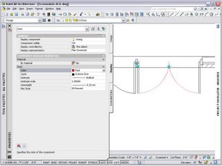
This tool works by selecting the element that you want to hide in the view, right clicking and picking Hide In View. You can select either Elements or Category.
 Once the element is hidden, you can select on the new Reveal Hidden Elements icon (the light bulb) on the View Control Bar at the bottom of the screen. When this is selected, all non-hidden elements will turn gray and you will get a bold magenta outline around your view to indicate that you are in a view hidden elements mode. Your hidden elements will be magenta as well. If you right click on a hidden element, you can select Unhide In View to unhide the element.

You can also turn temporary hidden elements into persistent hidden elements by selecting the element and picking on the Temporary Hide/Isolate icon (the sunglasses) on the View Control Bar. You will see a new option on the menu to Apply Hide/Isolate to View.

With the new Persistent Hide feature you can see what you want, and hide what you don't want to see and plot it that way. Hmmm... it actually works the way you want it to.
Hiding elements in Revit Architecture 2008 has some new features. The temporary hide feature in previous releases was just that-- temporary. When an element was hidden using the Temporary Hide tool, it would only be for that session. So, when a view with hidden elements was printed, all elements (whether hidden or not) would plot.
Let me introduce you to the new Persistent Hide tool. This will allow you to hide either individual elements or categories that will remain hidden and not plot. Prior to this tool, we would have to create some sort of view filter to hide elements.
This tool works by selecting the element that you want to hide in the view, right clicking and picking Hide In View. You can select either Elements or Category.
 Once the element is hidden, you can select on the new Reveal Hidden Elements icon (the light bulb) on the View Control Bar at the bottom of the screen. When this is selected, all non-hidden elements will turn gray and you will get a bold magenta outline around your view to indicate that you are in a view hidden elements mode. Your hidden elements will be magenta as well. If you right click on a hidden element, you can select Unhide In View to unhide the element.
You can also turn temporary hidden elements into persistent hidden elements by selecting the element and picking on the Temporary Hide/Isolate icon (the sunglasses) on the View Control Bar. You will see a new option on the menu to Apply Hide/Isolate to View.

With the new Persistent Hide feature you can see what you want, and hide what you don't want to see and plot it that way. Hmmm... it actually works the way you want it to.
Vista Patch for AutoCAD 2007
If you are trying to run AutoCAD 2007 on Windows Vista then listen up. We have been asked this question more times in the past several months than any other-- "How can I get it to work on Vista?"
Autodesk has released SP2 for AutoCAD 2007. Here is the link to download SP2. The only hiccup in the service patch is if you have already installed SP1. Due to a limitation in Service Pack 1, Service Pack 2 cannot be installed on Windows Vista with SP1 already installed. To install SP2, first uninstall and reinstall AutoCAD and then apply SP2 (without installing SP1.)
Autodesk has released SP2 for AutoCAD 2007. Here is the link to download SP2. The only hiccup in the service patch is if you have already installed SP1. Due to a limitation in Service Pack 1, Service Pack 2 cannot be installed on Windows Vista with SP1 already installed. To install SP2, first uninstall and reinstall AutoCAD and then apply SP2 (without installing SP1.)
Wednesday, March 21, 2007
Reader's Choice - Submit YOUR AU topic
AU 2007 will be here before you know it. Mark your calendars-- it will be held November 27-30 in Las Vegas. If you missed last year's event you will not want to miss this one.
I am opening up my blog for your suggestions. Let me know what topics you would like yours truly to cover. I will submit a course submittal on the top response. So here is your chance to make sure your topic is covered. It could be a topic in ADT or Revit. Just list your most desired topics in the comment section of this blog entry. What could be better than attending the world's best conference and attending a class that you personally suggested? Feel free to email me your suggestions with your contact information, and if AU selects the course I submit, I will contact you and recognize you at the event.
I am opening up my blog for your suggestions. Let me know what topics you would like yours truly to cover. I will submit a course submittal on the top response. So here is your chance to make sure your topic is covered. It could be a topic in ADT or Revit. Just list your most desired topics in the comment section of this blog entry. What could be better than attending the world's best conference and attending a class that you personally suggested? Feel free to email me your suggestions with your contact information, and if AU selects the course I submit, I will contact you and recognize you at the event.
Wednesday, March 07, 2007
Beefing Up for AutoCAD Architecture 2008!
Wow-- it just keeps asking for more and more. RAM that is. The new AutoCAD Architecture 2008 recommended system requirements are listed below. The one requirement that stands out is the 3 GB RAM or greater. Lets review for a moment. The 2006 version recommended 1 GB, the 2007 version recommended 2 GB, and now we are up to 3 GB. Where will it end?
CAD Managers better beef up those systems.
Recommended System Requirements
The following system requirements are recommended
for effective use of AutoCAD Architecture 2008:
• Intel® Pentium® 4 or AMD Athlon® processor,
3 GHz or greater
• Microsoft® Windows Vista™ or Windows® XP
(SP2)
• 3 GB RAM or greater
• 3.1 GB free disk space
• 1280 x 1024 monitor and display adapter capable
of 32-bit color
• 128 MB or greater, OpenGL®-capable workstationclass
graphics card
Wednesday, February 14, 2007
Snooping Under the Tree for Revit Architecure 2008
The presents under the Christmas tree continue to grow. It's Christmas for Revit users too! Here are some of the new features in Revit Architecture 2008.
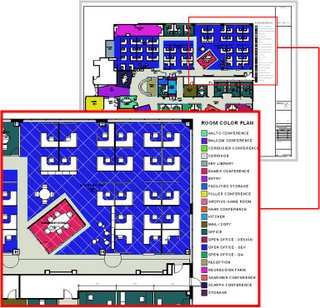
Color Fills
Color Fill enhancements provide better control over the creation, management and display of color fill patterns. Because the software offers more options for conveying design ideas in plan, Revit families such as furniture, equipment, and floors no longer hide behind color fills. Maximizing valuable drawing real estate, the color fill legend reports only those color fills represented in the active view.
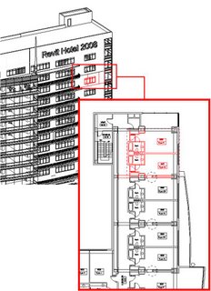
Revit Groups
Revit Groups, also known as repeating units, provide a modular design technique ideal for building types comprising of many rooms of similar size, shape, or configuration; such as, hospitals, hotels and apartment buildings. New workflow enhancements include the ability to load an RVT file as a group, save a group as an RVT, or change a group to a linked file. Additional enhancements include a new Group Edit Mode, which provides for the creation of elements while editing a group, numerous user interaction improvements, and the ability to exclude elements on an instance basis to accommodate special conditions.
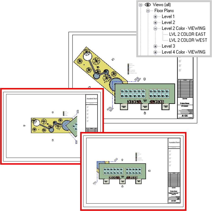
Dependent Views
Addressing the needs of firms managing large projects, dependent views provide a robust mechanism for segmenting projects across multiple sheet views. Coordination across sheets is automatically maintained between parent and dependant views helping to ensure model fidelity. All building information, including annotations, is kept accurate and up-to-date throughout the design process.

The addition of Dependent views bring about the creation of new tools in order to support that documentation technique. An additional crop region called the Annotation Crop provides the ability to crop annotations in the view and is accessible from the view properties; Match Lines have been introduced to denote the boundary between two (or more) dependent views; View Reference is a new annotation that provides an associative connection from a parent view to a dependent view. Similar to section heads, the View Reference will automatically display a view’s number and sheet number once the dependent view is placed onto a sheet.
History of Project: Prior to Revit Architecture 2008, Filled Regions were used, not only as intended, but also as a tool for obscuring or masking model geometry while detailing. The creation of a new Masking Region provides a tool with explicit masking functionality.
Benefit to User: The Masking Region tool provides a new method that is tailored for obscuring other elements. Masking Regions can be used in 2D model views as well as any 2D or 3D Revit Family (including detail elements and annotations).
With the new Masking Regions comes enhanced collaboration between Revit Architecture and AutoCAD. When viewed in DWG format, visual fidelity is maintained as Masking Regions obscure geometry beyond and appear opaque.
Autodesk VIZ and Autodesk 3ds Max Interoperability
Autodesk® VIZ or Autodesk® 3ds Max® software products can import or link 3D DWG™ files produced with Revit Architecture. Maximize your workflow by sharing model geometry, materials, and camera positions throughout the iterative design process. Create stunning photorealistic interior and exterior renderings to help sell your design ideas.
Graphical Overrides
Graphic overrides provide an ability to modify the graphic representation for a single element, thereby offering additional options for how elements appear in views. Graphic overrides also provide a visual method for hiding or revealing single elements or groups of elements by view. Settings are visually retained from session to session, reducing setup time in anticipation of plotting and printing.
File Linking
Offering more flexibility and easier management of linked model information, Revit links are organized within the project browser to provide new drag-and-drop management, together with quick and easy access to the Link Manager. Project visibility is significantly improved for the project team by displaying nested links within host files. The functionality of color fills is also enhanced as fills within host files are applied in linked views.
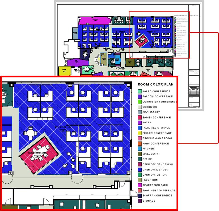
Color Fills
Color Fill enhancements provide better control over the creation, management and display of color fill patterns. Because the software offers more options for conveying design ideas in plan, Revit families such as furniture, equipment, and floors no longer hide behind color fills. Maximizing valuable drawing real estate, the color fill legend reports only those color fills represented in the active view.
Revit Groups
Revit Groups, also known as repeating units, provide a modular design technique ideal for building types comprising of many rooms of similar size, shape, or configuration; such as, hospitals, hotels and apartment buildings. New workflow enhancements include the ability to load an RVT file as a group, save a group as an RVT, or change a group to a linked file. Additional enhancements include a new Group Edit Mode, which provides for the creation of elements while editing a group, numerous user interaction improvements, and the ability to exclude elements on an instance basis to accommodate special conditions.

Dependent Views
Addressing the needs of firms managing large projects, dependent views provide a robust mechanism for segmenting projects across multiple sheet views. Coordination across sheets is automatically maintained between parent and dependant views helping to ensure model fidelity. All building information, including annotations, is kept accurate and up-to-date throughout the design process.
Match Lines & View References
The addition of Dependent views bring about the creation of new tools in order to support that documentation technique. An additional crop region called the Annotation Crop provides the ability to crop annotations in the view and is accessible from the view properties; Match Lines have been introduced to denote the boundary between two (or more) dependent views; View Reference is a new annotation that provides an associative connection from a parent view to a dependent view. Similar to section heads, the View Reference will automatically display a view’s number and sheet number once the dependent view is placed onto a sheet.
Masking Regions
History of Project: Prior to Revit Architecture 2008, Filled Regions were used, not only as intended, but also as a tool for obscuring or masking model geometry while detailing. The creation of a new Masking Region provides a tool with explicit masking functionality.
Benefit to User: The Masking Region tool provides a new method that is tailored for obscuring other elements. Masking Regions can be used in 2D model views as well as any 2D or 3D Revit Family (including detail elements and annotations).
With the new Masking Regions comes enhanced collaboration between Revit Architecture and AutoCAD. When viewed in DWG format, visual fidelity is maintained as Masking Regions obscure geometry beyond and appear opaque.
Autodesk VIZ and Autodesk 3ds Max Interoperability
Autodesk® VIZ or Autodesk® 3ds Max® software products can import or link 3D DWG™ files produced with Revit Architecture. Maximize your workflow by sharing model geometry, materials, and camera positions throughout the iterative design process. Create stunning photorealistic interior and exterior renderings to help sell your design ideas.
Graphical Overrides
Graphic overrides provide an ability to modify the graphic representation for a single element, thereby offering additional options for how elements appear in views. Graphic overrides also provide a visual method for hiding or revealing single elements or groups of elements by view. Settings are visually retained from session to session, reducing setup time in anticipation of plotting and printing.
File Linking
Offering more flexibility and easier management of linked model information, Revit links are organized within the project browser to provide new drag-and-drop management, together with quick and easy access to the Link Manager. Project visibility is significantly improved for the project team by displaying nested links within host files. The functionality of color fills is also enhanced as fills within host files are applied in linked views.
Tis the Season - AutoCAD Architecture 2008 New Features
It's my favorite time of year... right up there with Christmas! Here are some of the features that will be available in the upcoming AutoCAD Architecture 2008 release.
Area Documentation
Detail Documentation
Annotation Editing
Graphic Editing
Drawing Management
· Project name on Project Navigator
· Add folder in Project Browser
· Better handling of missing templates
Revision Communication
Area Documentation
- Space Layout Productivity
In AutoCAD Architecture, the ability to generate spaces automatically from objects & linework has been integrated directly into Palettes. This also provides the advantage of pre-specifying various options, such as style, to help streamline space creation.
- Automatic Update during design
Detail Documentation
- Master Format 2004 Support
Annotation Editing
- Annotative Scaling

Graphic Editing
- Object Graphic Control

- Graphic Control per Viewport
Drawing Management
- Sheets graphics coordinated with views
- Launch Projects via shortcuts
- General Fit and Finish
· Project name on Project Navigator
· Add folder in Project Browser
· Better handling of missing templates
Revision Communication
- Drawing Compare
Monday, February 12, 2007
Say Goodbye to ADT
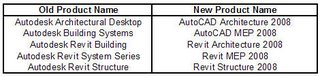
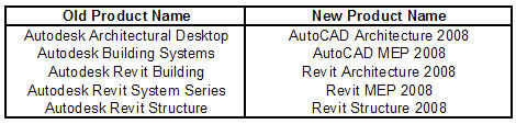
It's been rumored for years. Will Autodesk kill Architectural Desktop? Well, they have finally done it. Architectural Desktop will not be released in the new 2008 line of products. You will have to get used to calling it by its new name-- AutoCAD Architecture 2008. That's right, it's just a name change with some features that are really cool. Autodesk will be releasing their new 2008 product line soon, and one of the biggest changes that the Building Solution Division needs to get used to are the name changes. Below is a summary of the name changes for the 2008 releases.
 In the upcoming weeks I will give sneak peeks of some of the new features in the 2008 product lines. Stay tuned.
 In the upcoming weeks I will give sneak peeks of some of the new features in the 2008 product lines. Stay tuned.
Thursday, February 01, 2007
Is DEMO a Phase?
This morning I got a chance to read Steve's blog at Revit OpEd. He had a good article on how to show future phases by overlaying them onto sheet views. If you have not seen his blog, check it out. I want to expand on his article by explaining how to set up phases in your project, and defining the terminology for creating phases and filter states.
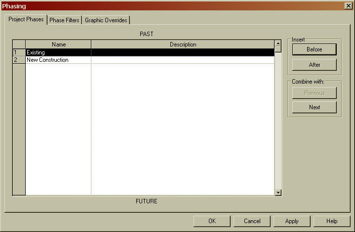
To begin setting up phases, you will find Phasing under the Settings pulldown menu. The dialog box is divided up into tabs. The first tab is where you set up the names of your phases. You will notice that the dialog box has Past on the top and Future on the bottom. It is important to order your phases chronologically. The default template comes with two default phases-- Existing and New Construction. You can rename the defaults or add new phases by clicking on the Before or After buttons in the Insert section.
Most people, including myself, think that Demolition is a phase in a project. With Revit, it is a Phase Status. Let me explain. You could have demolition in any or all phases of your project. It is just part of that particular phase. There are 4 default phase status' that can be used on every phase. You can set items to either Demolished, Existing, New, or Temporary in each phase. The following chart defines each of the phase states.

These settings can be applied in the Properties of each item. Simply tell Revit what phase the item is created in and what phase the item will be demolished in.

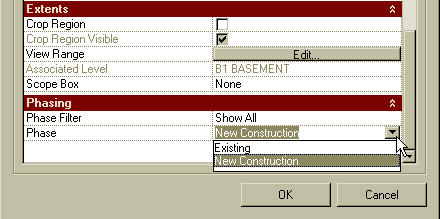
Once you have items set to the correct status, you will need to assign views to show the phase and apply the appropriate phase filter. You can do this in the View Properties.
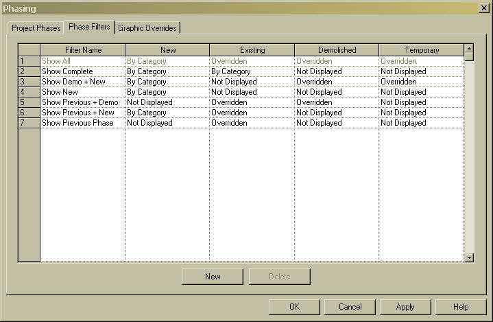
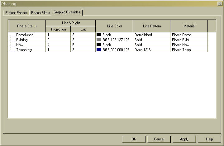
You can create additional Phase Filters or Override the Graphics in the main Phase dialog box under the Settings pulldown.
I hope this helps expand on what Steve wrote about. Phasing in Revit works well if you understand the concept of phases, phase states, and how to apply them to views.
Monday, January 29, 2007

Wednesday, January 10, 2007
Not Worrying About What You Don't Know
Well, my absence from blogging is over. I had a very nice Christmas season, and I am looking forward to a new year of blogging.
With a post title like this, I could go several directions. I could use this title to discuss the fear people have about switching over to the Revit Platform. After all, change can be a very big issue for some people. But this is not the direction I am heading. I could use this title to discuss how easy it is to gain a basic understanding of the Revit tools. How the tools work the way they ought to work, even if you don't know how to use them. But this is not the direction I am headed either. Okay, as we tell my father-in-law when he is telling us a story and he gets off subject... enough fluff!
I want to use this post to discuss the most common mistake people make when working on a Revit project. That is worrying about the details before it is time to worry about the details. Revit is a modeling program. Most people tend to want to be as accurate as possible, and show as much detail as they can to "wow" their customers with 3D perspectives. I am here to tell you, that if you spend too much time worrying about specific details in the design phase, then you are missing the point.
You should use Revit as a design tool. When I am in a design stage of a project, I don't care what size the column needs to be or what the exact make-up of the exterior walls are. I just want to focus on the design intent and make sure that the spaces work. As CAD drafters, we sometimes get too caught up in the details too early in the game.
Let me introduce a new Revit term to you. It's called Space Holders. You can use space holders to quickly block out something in your model that you will eventually go back and revise to the correct component. This will allow you to keep focused on the design, not the details. For example, when laying out a building, I know that I will have to have columns in my building, but I may not know where, what type, or the exact size of the column until later in the game. Typically, we give our structural engineers a base plan and they provide us with the column spacing and sizes. So in the early stages, I may just want to use a standard box column in my plans as a preliminary column spacing plan. After my engineer designs the structural model, I can simply exchange my place holder columns with the correctly sized columns by replacing the family. This will save me time and frustration in the design phase.
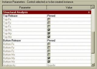
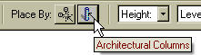
While I am on the subject of columns, let me take the time to tell you the difference between Architectural columns and Structural columns in Revit. The architectural column is found on the Modeling Design Bar while the structural column is found on the Structural Design Bar. They work and feel basically the same. The only difference between the two is that the structural columns have additional parameters that the engineer can use to extract to his structural design program to size the member. These parameters will be grayed out unless you are running Revit Structural.
If you are working with an engineer that is using Revit, then by all means, use structural columns as opposed to architectural columns. If your engineer is not using Revit, then it really doesn't matter. You can use architectural columns as wrap arounds and structural columns as the actual column. If you are doing this, then when placing the structural columns, you can insert them by selecting your architectural column wrap arounds as the mode of inserting.
 This will save time and insure that your columns and the structural columns are connected. If one moves, the other will move with it. Pretty neat trick to make sure your wrap arounds are in the correct location.
Enough fluff! Back to my original post title. To sum it up, don't get caught up in the details too early in the game. Use place holders when needed, and just make sure that you eventually go back and replace the place holders with the correct components when that knowledge is gained.
With a post title like this, I could go several directions. I could use this title to discuss the fear people have about switching over to the Revit Platform. After all, change can be a very big issue for some people. But this is not the direction I am heading. I could use this title to discuss how easy it is to gain a basic understanding of the Revit tools. How the tools work the way they ought to work, even if you don't know how to use them. But this is not the direction I am headed either. Okay, as we tell my father-in-law when he is telling us a story and he gets off subject... enough fluff!
I want to use this post to discuss the most common mistake people make when working on a Revit project. That is worrying about the details before it is time to worry about the details. Revit is a modeling program. Most people tend to want to be as accurate as possible, and show as much detail as they can to "wow" their customers with 3D perspectives. I am here to tell you, that if you spend too much time worrying about specific details in the design phase, then you are missing the point.
You should use Revit as a design tool. When I am in a design stage of a project, I don't care what size the column needs to be or what the exact make-up of the exterior walls are. I just want to focus on the design intent and make sure that the spaces work. As CAD drafters, we sometimes get too caught up in the details too early in the game.
Let me introduce a new Revit term to you. It's called Space Holders. You can use space holders to quickly block out something in your model that you will eventually go back and revise to the correct component. This will allow you to keep focused on the design, not the details. For example, when laying out a building, I know that I will have to have columns in my building, but I may not know where, what type, or the exact size of the column until later in the game. Typically, we give our structural engineers a base plan and they provide us with the column spacing and sizes. So in the early stages, I may just want to use a standard box column in my plans as a preliminary column spacing plan. After my engineer designs the structural model, I can simply exchange my place holder columns with the correctly sized columns by replacing the family. This will save me time and frustration in the design phase.
While I am on the subject of columns, let me take the time to tell you the difference between Architectural columns and Structural columns in Revit. The architectural column is found on the Modeling Design Bar while the structural column is found on the Structural Design Bar. They work and feel basically the same. The only difference between the two is that the structural columns have additional parameters that the engineer can use to extract to his structural design program to size the member. These parameters will be grayed out unless you are running Revit Structural.

If you are working with an engineer that is using Revit, then by all means, use structural columns as opposed to architectural columns. If your engineer is not using Revit, then it really doesn't matter. You can use architectural columns as wrap arounds and structural columns as the actual column. If you are doing this, then when placing the structural columns, you can insert them by selecting your architectural column wrap arounds as the mode of inserting.
 This will save time and insure that your columns and the structural columns are connected. If one moves, the other will move with it. Pretty neat trick to make sure your wrap arounds are in the correct location.
Enough fluff! Back to my original post title. To sum it up, don't get caught up in the details too early in the game. Use place holders when needed, and just make sure that you eventually go back and replace the place holders with the correct components when that knowledge is gained.
Subscribe to:
Posts (Atom)